Schemat modułu KIS-3R33S - V1
oryginalna wersja przetwornicy DC-DC KIS-3R33S
oryginalna wersja przetwornicy DC-DC KIS-3R33S
Przetwornica DC-DC na układzie MP2307DN
Specyfikacja KIS-3R33S
| Product Info: | 3A, 23V, 340kHz Synchronous Rectified Step-Down Converter |
| Description: | The MP2307 is a monolithic synchronous buck regulator. The device integrates 100mΩ MOSFETS that provide 3A of continuous load current over a wide operating input voltage of 4.75V to 23V. Current mode control provides fast transient response and cycle-by-cycle current limit. An adjustable soft-start prevents inrush current at turn-on and in shutdown mode, the supply current drops below 1µA. This device, available in an 8-pin SOIC package, provides a very compact system solution with minimal reliance on external components. |
| Vin (Min) (V): | 4.75 |
| Vin (Max) (V): | 23 |
| Iout (Max) (A): | 3 |
| Iq (Typ) (mA): | 1.3 |
| Vfb (V): | 0.925 |
| Freq (kHz): | 340 |
| Soft Start: | External |
| Package: | SOIC8E |
| Typical Application: | 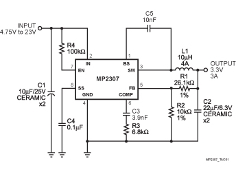
The typical application for MP2307 is not real circuit in KIS-3R33S. |
| Efficiency Curve: | 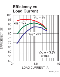 |
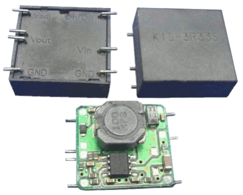
| KIS-3R33S: |  |
| KIS-3R33S schemat: |
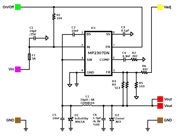 |
MP2307DN
| 1 BS | High-Side Gate Drive Boost Input. BS supplies the drive for the high-side N-Channel MOSFEswitch. Connect a 0.01µF or greater capacitor from SW to BS to power the high side switch. |
| 2 IN | Power Input. IN supplies the power to the IC, as well as the step-down converter switches. Drive IN with a 4.75V to 23V power source. Bypass IN to GND with a suitably large capacitor to eliminate noise on the input to the IC. See Input Capacitor. |
| 3 SW | Power Switching Output. SW is the switching node that supplies power to the output. Connect the output LC filter from SW to the output load. Note that a capacitor is required from SW to BS to power the high-side switch. |
| 4 GND | Ground (Connect the exposed pad to Pin 4). |
| 5 FB | Feedback Input. FB senses the output voltage and regulates it. Drive FB with a resistive voltage divider connected to it from the output voltage. The feedback threshold is 0.925V. See Setting the Output Voltage. |
| 6 COMP | Compensation Node. COMP is used to compensate the regulation control loop. Connect a series RC network from COMP to GND. In some cases, an additional capacitor from COMP to GND is required. See Compensation Components. |
| 7 EN | Enable Input. EN is a digital input that turns the regulator on or off. Drive EN high to turn on the regulator; low to turn it off. Attach to IN with a 100kΩ pull up resistor for automatic startup. |
| 8 SS | Soft-Start Control Input. SS controls the soft-start period. Connect a capacitor from SS to GND to set the soft-start period. A 0.1µF capacitor sets the soft-start period to 15ms. To disable the soft-start feature, leave SS unconnected. |
• These modules are widely used on:
• Distributed Power Systems
• Networking Systems
• FPGA, DSP, ASIC Power Supplies
• Green Electronics/Appliances
• Notebook Computers
• Size (L x W x H): Approx. 21 x 20 x 7mm
• Input Voltage: 4.75 - 23V DC • Output Voltage: 3.3V (can be modified to 0.925 - 20V)
• Efficiency: Up to 95%
• Output Current: Rated 3A, max up to 4A peak
• Internal Frequency: Fixed 340KHz
• Protection: Cycle-by-cycle over current protection
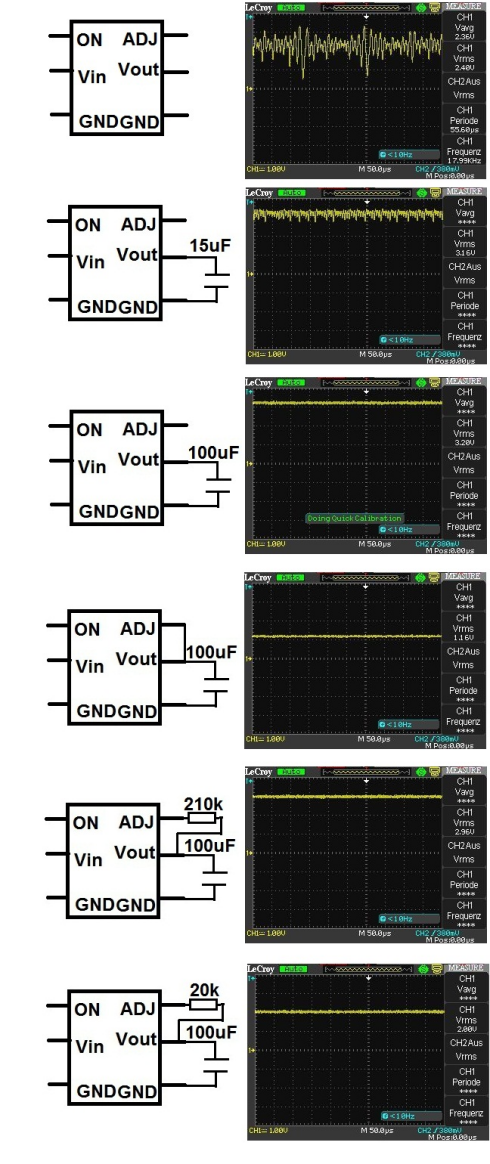
Wpływ pojemności kondensatora dodanego na wyjściu modułu obrazują wykresy z oscyloskopu: